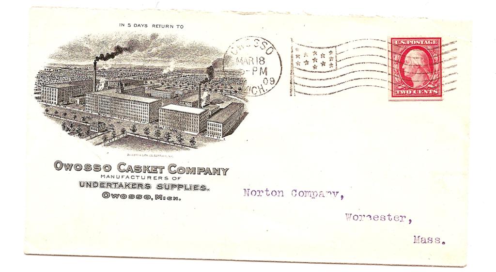
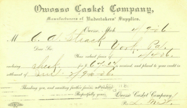
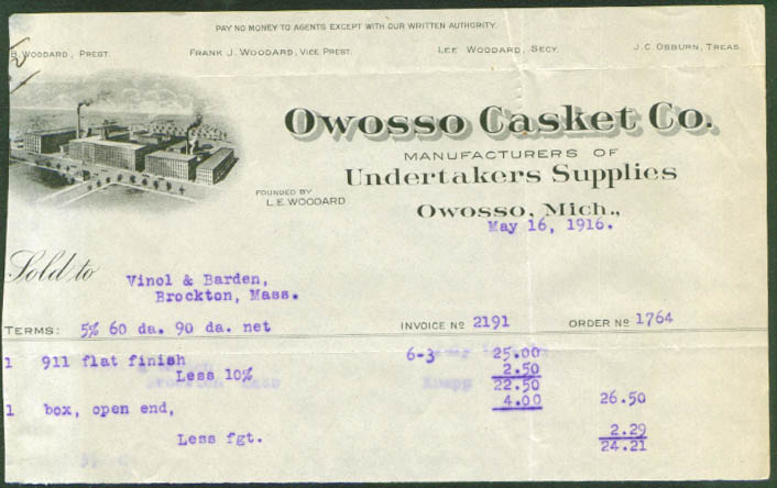
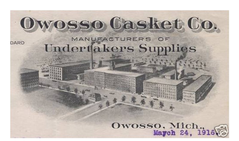
Owosso Casket Company
Owosso, Michigan
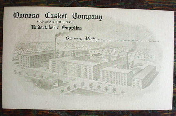
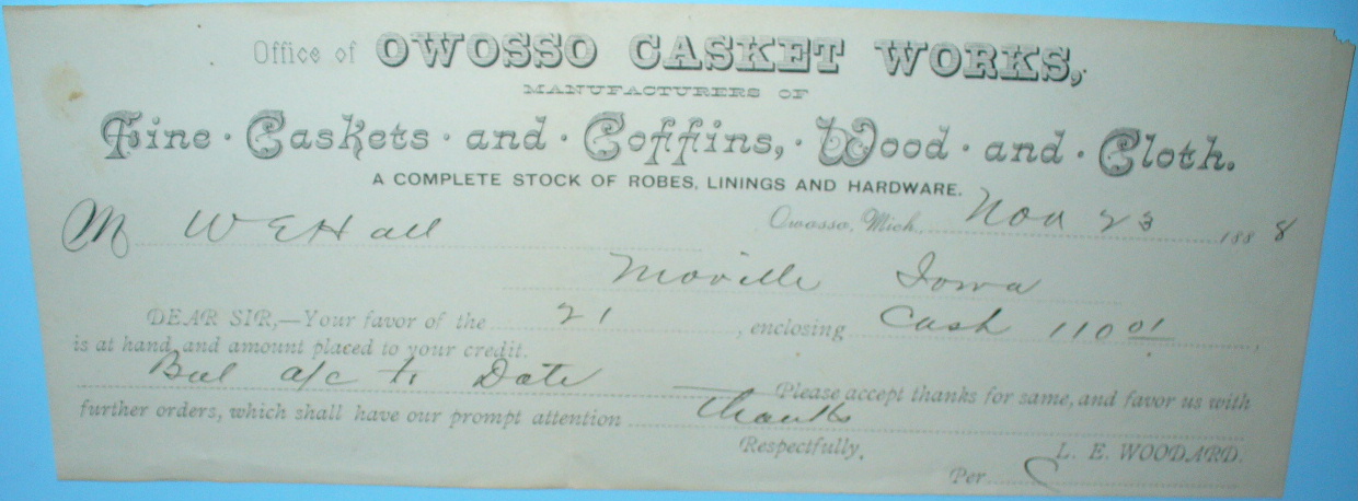
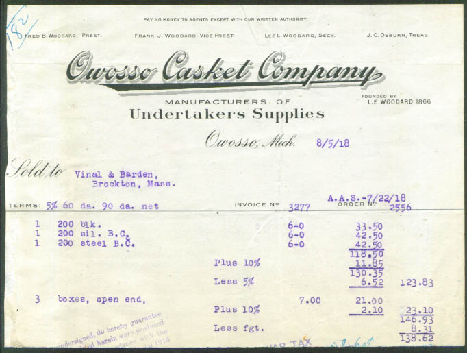
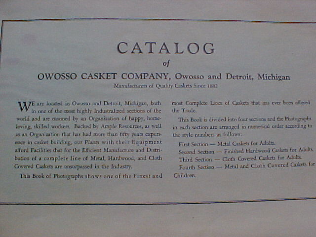
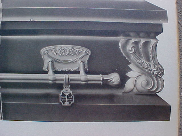
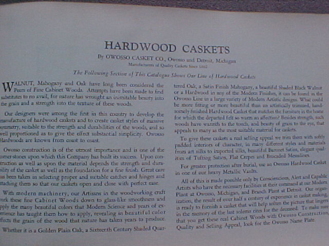
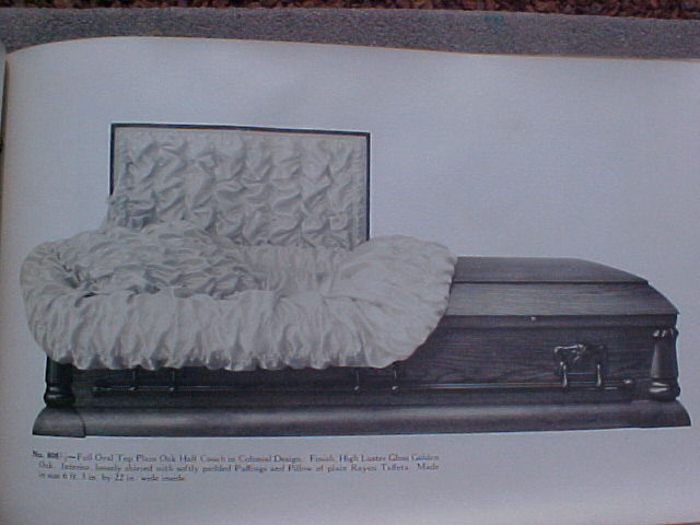
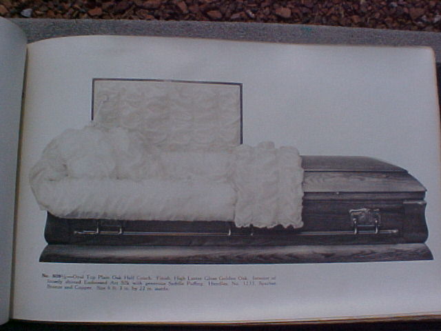
The Owosso Casket Co. was owned by the Woodard family and were manufacturing caskets as early as 1882 according to an Owosso Casket Company catalog, shown below.
The company claims fame as having supplied two presidents with coffins, William McKinley, after he was assassinated in Sept. 1901 and former President Benjamin Harrison, who died March 13. 1901.
Owosso Casket Co. was known as the world's largest casket maker at one time.
It was incorporated in 1901, Capitol $100,000, Fred B. Woodard, President, and the office was at Elm and Genesee Streets.
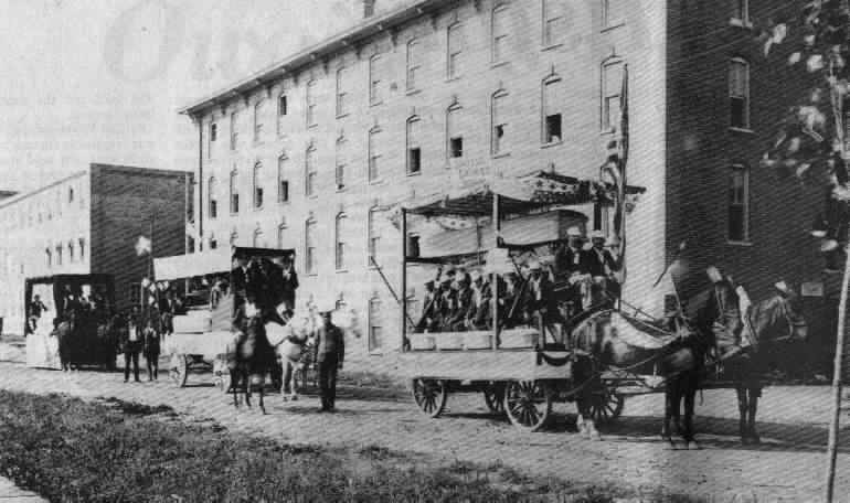
Below, the Owosso Casket Co. as it appeared in about 1900, as the employees prepared for the annual Labor Day Parade.
In 1918, due to the flu epidemic which caused the deaths of hundreds of people in the U.S., the local paper reported the Owosso Casket Co. was turning out caskets at the rate of 150 per day and they are far behind their orders.
The casket company closed in the 1940's - 1950's.
More about the Woodard Furniture Company
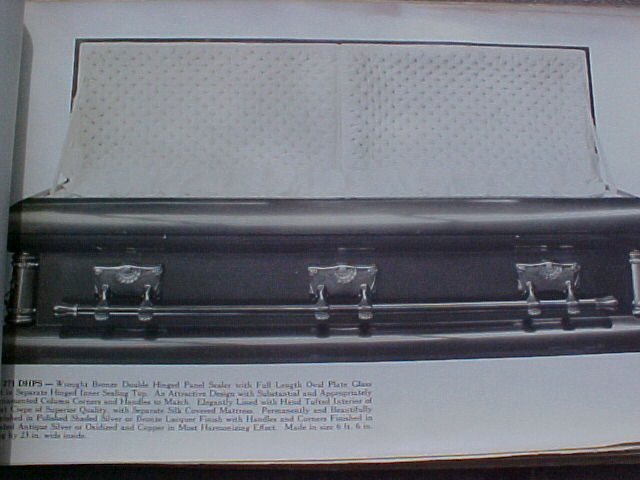
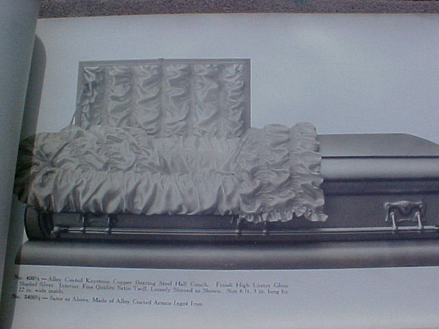
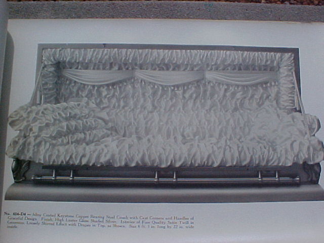
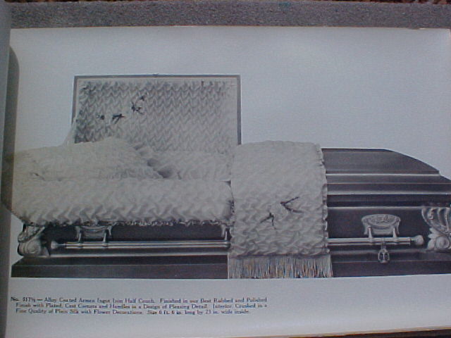
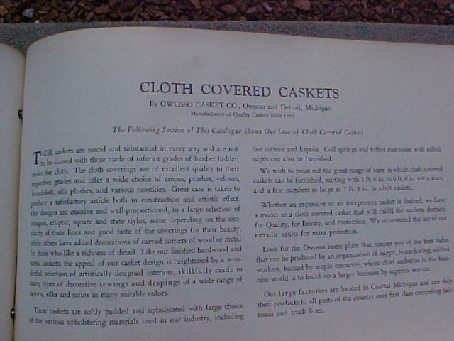
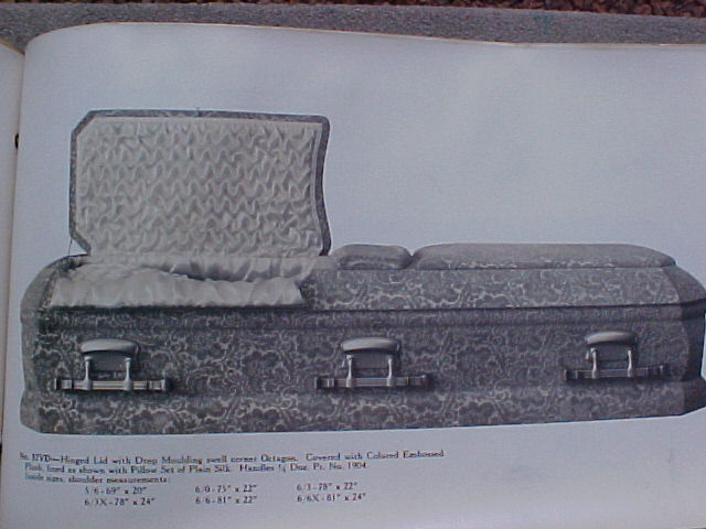
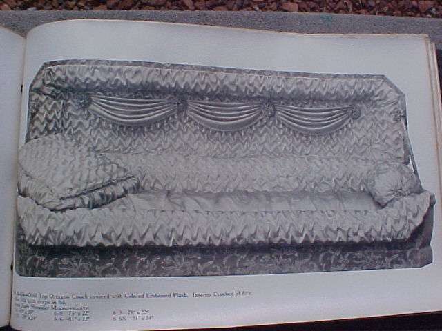
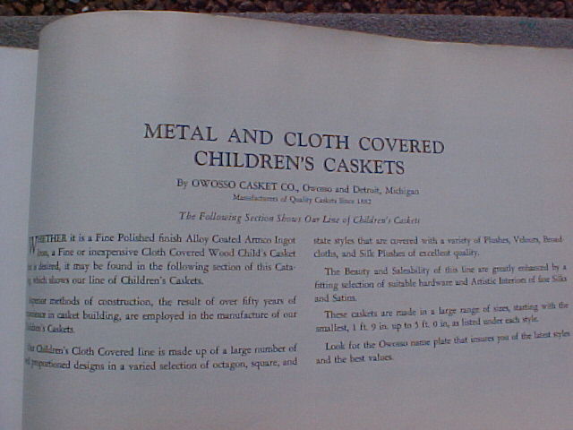
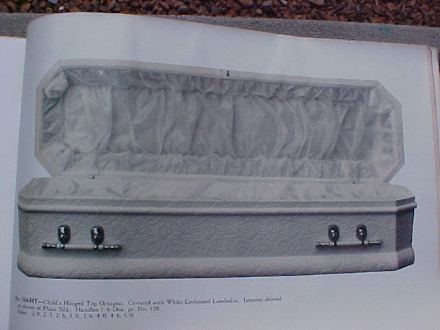
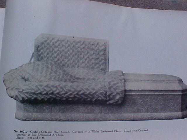
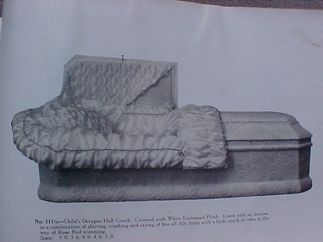
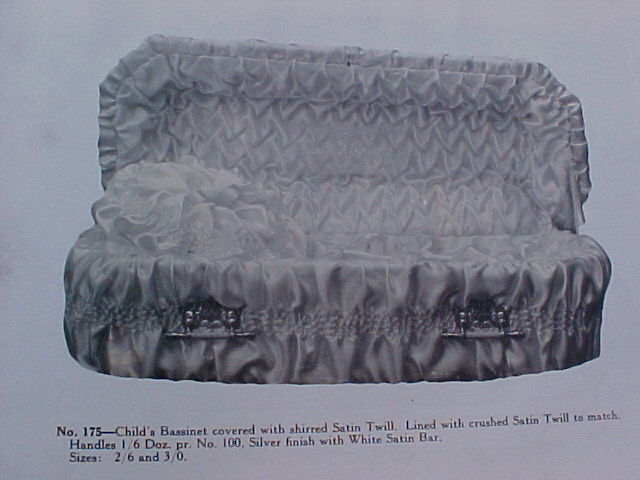
Just a few pages from the early 1900's era catalog
CHARLES A RUEBEKAM OF OWOSSO MICHGAN ASSIGNOR TO LYMAN E. WOODARD OF SAME PLACE
LID FOR BURAL CASKETS
SPECIFICATON forming part of Letters Patent No. dated August 27, 1895
Application filed February Serial No
Improve the construction of the lid
To all whom it may concern:
Be it known that CHARLES A RUEBEKAM a citizen of the United States residing at Owosso in the
county of Shiawassee and State of Michigan have invented certain new and useful improvements in
Lids for BurialCaskets and do hereby declare that the following is a full clear and exact description
of the same reference being had to the annexed drawings making a part of this specification and to the
letters of reference marked thereon.
The present invention has relation to that class of burialcaskets provided with hinged or sliding lids and the object thereof is to hereinafter described and subsequently pointed out in the claim.
Figure 1 of the drawings represents a portion of the top of a burialcasket in perspective showing the sliding and hinged lid partly open Fig 2 a longitudinal section with the lid closed Fig 3 a transverse section taken on line x x of Fig 2 Fig 4 a detail view in perspective showing one of the guides upon the under side of the lid Fig 5 is a perspective of a casket showing the cover complete in the accompanying drawings A represents a portion of the top of a burialcasket which may be of any suitable design and ornamentation and if desired covered with black cloth or other material as found preferable.
This top as shown in the drawings is located at the head of the casket and has the usual face opening in which slides the hinged lidsections B C said opening having the usual glass faceplate D which is secured in place in any wellknown and desirable manner. The top A upon the sides of the opening has longitudinal grooves a to receive guides b secured to the under side of the lidsection C whereby said section is held in position when closed and also guided in its sliding movement.
Any suitable guides or arrangement of grooves or recesses may be provided in place of those shown and to lock the lidsection B in position when closed the end of the section is provided with a pin c which engages a hole d in the end of the caskettop A as shown in Fig 2 of the drawings.
The lidsection B is made thinner than the section C in order to enable a raised nameplate to be used without interfering with the glass faceplate D so that when said section is thrown up and back into position the plate will be exposed.
Suitable flexible connections e of black ribbon cloth or other material may join the two lidsections at the point where they are hinged to serve as means in preventing the 6o section B from being thrown too far back and hold it in an inclined position.
The hinged lidsection C is secured in its closed position by means of a suitable catch E which is spring actuated and is preferably 65 provided with a cord f for operating it and a spring g for retaining the catch in engagement with the keeper h which may be of any wellknown form as may also the spring actuated catch. When it is desired to open the lid the catch is raised by the cord until it is out of engagement with the keeper which will also raise the end of the section C to a slight degree in this position the lidsection C as well as the section B is moved forward until the stop i upon the under side of the section C strikes the abutment or portion of the top A as shown at k.
The lidsections will now be brought forward to their greatest extent after which the section B is thrown up and go back The lidsections will now be brought forward to their greatest extent after which the section B is thrown up and go back in position to expose the faceplate D nearly its entire length.
When closing the lid, the knob 1 is taken hold of and the lidsection to which it is connected is lowered and the two sections moved back in a closed position as shown in Fig 2 of the drawings the pin c of the section B engaging with the hole d to lock the section and prevent its being raised except when both sections are moved forward.
Any suitable means may be employed for automatically locking the lidsection B in a closed position although in the present instance the pin is considered the most simple means for attaining this result. The sections B C may have an ornamental bead m around their edges and projecting therefrom a sufficient distance to overlap the upper side of the caskettop A and thus form a support for said sections. The inner ends of on the sections B C which are hinged together are cut in the form shown or maybe curved, semicircular elliptical octagon or any other preferred shape found most desirable.
Having now fully described my invention what claim as new and desire to secure by Letters Patent is
A casket cover having an opening through
it that is closed with the glass D and suitable
raised guides applied to the top of the cover
around the opening above the glass combined
with a sliding cover composed of two sections
hinged together and placed in the guides the
front section having a sliding movement and
also adapted to be raised at one end while the rear section has only a sliding movement for the purpose of
moving the front section r backward substantially as shown.
In testimony that claim the above have hereunto subscribed my name in the presence of two witnesses: CAS A RUEBEKAM
Witnesses:
LOUS FLOCKNGER and GRACE MERSHON
Patented Dec. 14, 1897
UNiTED STATES PATENT OFFICE
WILLIAM S. JONES OF OWOSSO MCHGAN ASSIGNOR TO OSCAR D. BYERS OF SYRACUSE, NEW YORK
BURIAL CASKET SPECIFICATON forming part of Letters Patent No dated December 14, 1897
Application filed May 11, 1896
To all whom it may concern:
Be it known that WILLIAM S. JONES, a citizen of the United States residing at Owosso, county of Shiawassee, State
of Michigan have invented a certain new and useful mprovement in Burial Caskets and declare the following
to be a full clear and exact description of the invention such as will enable others skilled in the art to
which it appertains to to make and use the same reference being had
to the accompanying drawings which form
a part of this specification.
My invention has for its object certain new and useful improvements in burial caskets and it consists of the construction combination and arrangement of devices hereinafter described and claimed and illustrated in the accompanying drawings in which Figure 1 is a view in side elevation showing the facelid folded back. Fig 2 is a plan view showing the folding sections of the covemolding in dotted lines in opened position the facelid B being folded back in opened position. Fig 3 is a crosssection on the facelid and folding sections of the covemolding being in closed position. Fig 4 is a similar view showing the folding sections of the covemolding in opened position.
The object of my invention is to provide a burial casket with a facelid which may be removed or folded backward out of the way together with folding sections of the covemolding whereby a fuller view may be more readily had of the remains within the casket when said folding sections are in opened position whereby a neat and tasteful appearance is given to the casket and whereby a support is furnished for flowers and the like at the head of the casket.
Carry out my invention as follows:
A represents the body of a casket which may be constructed in any suitable manner or form
B is a facelid hinged to the coverpanel B' as shown at b but my invention contemplates either the hinging
of the facelid to turn it back out of the way or the removal of the facelid as by a detachable hinge or
analogous device.
C denotes the covemolding of any desired form Serial No 061 (No model)
At the head of the casket my invention contemplates cutting out two or more sections (indicated by the numerals 12 3) said sections being cut vertically into the molding a desired distance but not through the molding the base C of the molding adjacent to the head remaining intact and resting upon the body A of the casket.
The sections 1 2 3 are separated horizontally from the base C of the molding and are hinged to said base C as indicated at c. Thus the section 1 is shown hinged at c c to the end of the base C as indicated more particularly in Fig 2, while the sections 2 and 3 are each hinged as shown at 65 on opposite sides of the casket to the base C of the cove.
The base C of the cove thus extends integrally around the upper edge of the body do not limit myself to hinging the section 1 to the base as it might be left integral with the base the two lateral sections 2 and 3 being hinged to the base C of the covemolding prefer to cut the sections 2 and 3 at the head of the casket at such points that they may be held firmly in closed position when the facelid B is closed.
The head end of the facelid is provided with a suitable catch or lock as indicated at D to fasten into the section 1 will be observed that the base C' of the molding inwardly overhangs the upper edges of the body thereunder thereby covering the upper edges of the lining of the casket.
The hinges c are preferably connected with the outer lower edge of said sections in closed position whereby said sections will fold over freely to present the surfaces of their inner edges uppermost to form with the upper surface of the base C a support or "shrinesurface" equal to the combined widths of the base C and the adjacent section.
Suitable lining or finishing material of a flexible nature as indicated by the numeral 4 may be engaged to cover said shrinesurface said lining readily folding up when the sections are closed.
What claim as my invention is:
1 The combination with a casketbody of a covemolding divided longitudinally and having the sections
thereof hinged together at their outer edges and the lid supported on too the upper section of said molding
2 The combination with the casketbody of a covemolding having the portion around the head of the
casket divided longitudinally in a horizontal
plane and the upper portion thereof severed vertically into a head section
and side sections 2 and 3 and hinged to the outer edges of the lower portions of the covemolding
substantially as set forth.
In testimony whereof sign this specification in the presence of two witnesses
WILLIAM S JONES
Witnesses:
N.S. WRGHT and JOHN F. MILLER
1890 WOODARD Grave Casket Burial Coffin Patent 17685
(No Model) No L E WOODARD COFFN FASTENER Patented Jan 28 1890 c vti evtiko z c 1c t tLLS' Qtkc Le1J v i l4eaaea N PETERS PhonyLahopnpher WaaSsgfen 0: C UNTED STATES PATENT OFFCE LYMAN E WOODARD OF OWOSSO MCGAN COFFNFASTENER SPECFCATON forming part of Letters Patent No dated January 28 1890 Application filed November 12 1889 Serial No 030 (No model) 5 35 40 To all whom it may concern: Be it known that LYMAN E WOODARD a citizen of the United States residing at Owosso in the county of Shiawassee and State of Michi gan have invented certain new and useful mprovements in CoffinLid Fasteners and do hereby declare that the following is a full clear and exact description of the same reference being had to the annexed drawings o making a part of this specification and to the letters of reference marked thereon This invention relates to certain new and useful improvements in coffinlid fasteners and is designed more particularly as an im i5 provement upon the device for which obtained a patent dated August 27 1889 No 060 t has for its object among others to provide an improved fastener which can be read 2o ily operated both to open or close the coffin or casket the fastening being so arranged that both a sidewise and endwise movement of the lid is required to remove or properly attach it 25 The invention in the present case resides in the peculiar combinations and the novel construction arrangement and adaptation of parts all as more fully hereinafter described shown in the drawings and then particularly 30 pointed out in the appended claims The invention is clearly illustrated in the accompanying drawings which with the letters of reference marked thereon form a part of this specification and in which Figure 1 is a vertical longitudinal section through a coffin or casket showing my improved fastenings applied thereto Fig 2 is a transverse section through the line x x of Fig 1 Fig 3 is a perspective view of the improved fastener removed and in a reverse position with the keeper in dotted lines in its position relative to the fastener Fig 4 is a perspective view of the keeper detached and reversed Fig 5 is a detail showing a 45 modified form of keeper Like letters of reference indicate like parts throughout the several views Referring now to the details of the drawings by letter A designates a coffin or casket 50 of any of the usual forms and provided with a lid or cover B a designating the head and b the foot of the coffin or casket At the foot of the coffin or casket attach a keeper c set flush with the upper face there of and notched upon its inner edge with a 55 space beneath the same for the passage of the end of the lip cl attached to the under side of the end of the lid as shown clearly in Fig 1 Upon one side of the casket or coffin upon the upper edge thereof place a like 6o keeper e designed to receive a like lip or tongue f attached to the under side of the lid at the side as shown clearly in Fig 2 n order to place the lid upon the casket it is necessary to first elevate one end and engage 65 the end lip d beneath its keeper then drop the lid to a horizontal position and give it a slight movement sidewise toward the keeper e when the lip f will engage beneath the said keeper as shown in Fig 2 Thus it is nee 70 essary to give the lid first a movement endwise and then at right angles thereto After it has been given its sidewise movement and as it seats itself in place upon the casket or coffin it is locked in this position by means 75 of my improved fastener which will now describe Upon the under side of the lid opposite the keeper e and lip f is the plate C which serves as a keeper being provided with suitable holes for the passage of the screws 8o or other securing means and formed with a rightangled portion g which is beveled inward toward the center of the lid and is provided with an elongated slot or opening li for the passage of the latch hereinafter de 85 scribed D is a plate provided with suitable holes for the passage of the means which are employed to secure it to the upper edge of the casket or coffin it being designed to be seated 90 in a recess or chamber therein This plate is also formed upon its under side with two rightangled portions i and j one j being slightly inclined to form a perpendicular to correspond with the inclination of the inner 95 wall of the coffin when designed for use upon coffins in which the inner wall is inclined but of course when designed for coffins having vertical walls this portion will not be inclined These portions i and j are not in the same plane but one is out of line with the other and both are provided with slots or openings as shown in Fig 3 for a purpose clearly shown in said figure 00 2 E is an elbowlever pivoted at its elbow as at k to the plate D with one arm passed through the opening in the rightangled portion i and turned over upon itself to form a 5 fingerhold by which it may be more easily operated The other arm of this lever extends normally lengthwise of the plate D and at its free end is formed with a rightangled portion beveled as shown in Fig 3 to form lc) the latch and passed through the opening in the portion j as shown in said Fig 3 F is a spring attached at one end to the portion i of the plate and at the other end attached to the longitudinal arm of the elbow curved latch working through a hole in the 15 lever E near its free end other portion and a spring attached at one end to the free end of the horizontal arm which extends parallel with the plate and at the other end attached to the rightangled portion through which the handle portion of the lever works substantially as shown and described n testimony that claim the above have hereunto subscribed my name in the presence of two witnesses LYMAN E WOODARD Witnesses: E W WOODWARD GEO G FOWLER with said plate and having one aria working through an opening in one of said rightangled portions and the other end or arm of said lever shaped into a latch and working through an opening in the other portion substantially as described and shown 2 The combination with a keeper of a plate formed with rightangled portions in different planes an elbowlever pivoted to said plate with one arm working through a slot in one of said portions and the other extending substantially parallel with the plate and shaped at its free end into a beveled or The springcatch above described acts in conjunction with the catches at the end and side of the lid to form a secure fastening for the lid at both the head and foot of said 20 casket n Fig 5 have shown the portion g as formed upon a curve with which the end of the bolt engages to draw the lid down closer the end of the bolt being also inclined to fa 25 cilitate this operation What claim as new is 1 An improved fastening device for coffinlids consisting of a plate formed with rightangled portions a lever pivotally connected 30 35 40 45
1897 RUEBEKAM Grave Casket Burial Coffin Patent 17560
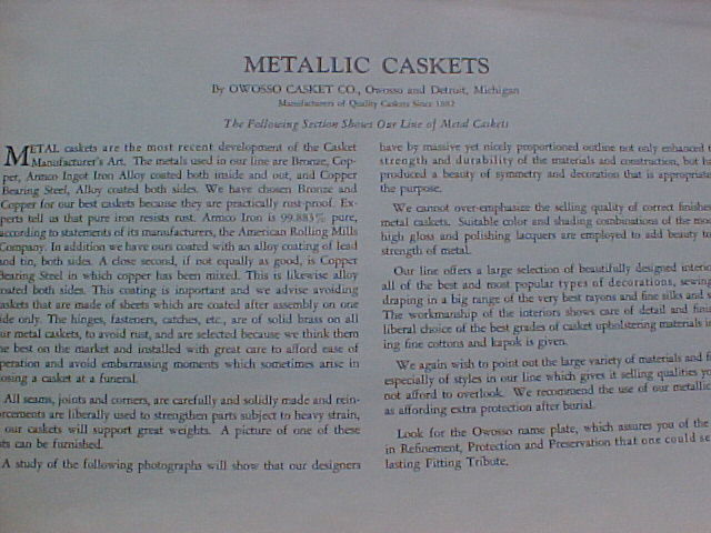
(No Model) No C A RUEBEKAM BURAL CASKET Patented Aug 17 1897 5 f7 "A V4fAVAk WTNESSES: BY NVE TOR 4a' 9r?4fd6aLrx ATTORNEYS THE HOpFL PETEO9 CO 0T0UT wHCTLO L UNTED STATES PATENT OFFCE CHARLES A RUEBEKAM OF OWOSSO MCHGAN ASSGNOR TO LYMAN E WOODARD OF SAME PLACE BURALCASKET SPECFCATON forming part of Letters Patent No dated August 17 1897 Application filed June 28 1897 Serial No (No model) 35 drawings forming a part of this specification To all whom it may concern: Be it known that CHARLES A RUEBE KAln of Owosso in the county of Shiawassee and State of Michigan have invented a new and mproved BurialCasket of which the following is a full clear and exact' description The object of the invention is to so con struct the covers or lids or molding of a casket ro around that portion at which the face of the occupant is to be exposed that the position of the covers or lids on the molding may be expeditiously and conveniently changed so as to expose more or less of the person and 15 whereby hooks stationarily placed on the covers or lids will serve in conjunction with keepers on the molding to hold the lids or covers in either one of the positions in which they may be placed 20 Another object of the invention is to provide for a change in the position of the lids or covers of the casket in such manner that the keepers for the covers or lids will hardly be discernible in the molding and will not in 25 the least detract from its appearance Another object of the invention is to provide for the entire removal of the covers or lids from the casket when such disposition is required 30 The invention consists in the novel construction and combination of the several parts as will be hereinafterfully set forth and pointed out in the claims Reference is to be had to the accompanying in which similar characters of reference indicate corresponding parts in all the figures Figure 1 is a plan view of the molding for the caskettop or that portion at which the face is to be viewed illustrating the manner in which the covers are secured thereto one of the covers being shown as broken away Fig 2 is a section taken transversely through a portion of the said molding and said covers and Fig 3 is a detail perspective view of an end portion of one of the covers or lids A represents the molding which is to ex tend around the head and bust portion of the body and which is sometimes designated in 5o the trade as the "cove" The upper portion or strip of the said molding or cove is providecl at each side near each end with a recess 10 Each recess 10 is spanned at the top by a keeperplate 11 and at the outer side by a second keeperplate 12 one keeperplate at each opening being at an angle to the other Each keeperplate is provided with a longitudinal slot 13 and what may be termed the "outer" side wall of each slot 13 is bent inward and downward to form a lip 14 as is 6o best shown in Fig 2 Each lid or cover B is made in two sectionsnamely a bodysection 16 and an outer side section 15 The opposing walls of the two sections are beveled in opposite directions forming between 65 the sections when the cover or lid is in closed position a Vshaped opening 16a as shown in Fig 2 Hinges 17 connect the two sections of each cover or lid at the top extending over the Vopening 16a as is also illustrated in 70 Fig 2 From the bottom portion of the outer section 15 of each cover or lid usually two hooks 18 are downwardly and outwardly projected and each hook as illustrated in Fig 3 consists of a curved body portion a the concaved face whereof is upward and a downwardly and outwardly inclined tip a' The keepers 11 and 12 are concealed by the covering 19 provided for the molding or cove but the said covering is provided with a slot So over the respective openings 13 in the said keeperplates n operation the hooks 1S are made to enter the openings in the upper or horizontal keeperplates and when so entered the cov 85 ers or lids may be closed entirely over the opening in the molding or the cove as shown in positive lines in Fig 2 or each lid or cover may be carried outward so as to disclose the said opening the end sections of the lids or 90 covers being then in a vertical position and the body portions in a horizontal position as shown in dotted lines in Fig 2 Under this disposition of the covers or lids the opening within the cove or molding will be entirely exposed but it is sometimes desirable to have the opening seem larger which result may be accomplished by providing a border for it consisting of the molding itself and carrying the covers or lids some distance from the opening to form a second frame or dressing therefor This latter arrangement may be 5 40 45 55 75 95 goo 2 secured by simply removing the covers or lids from engagement with the upper or horizontal keepers 11 and causing the hooks 18 of the covers or lids to enter into the outer or 5 side keepers 12 as is also shown in dotted lines in Fig 2 t is evident also that the covers or lids may be entirely removed from connection with the molding or cove if so desired and that when the hooks 1S enter either io of the keepers 11 or 12 the said hooks will serve as hinges and will act to effectually hold said covers or lids in engagement with the molding or cove The concaved surfaces of the hooks 1S 15 when the lids or covers are carried to an open position will engage with the upper surfaces of the lips 14 which are convexed while the tips a' will engage with the under faces of the keepers adjacent to the inner edges of 20 their openings 13 as is shown in dotted lines in Fig 2 laving thus described my invention claim as new and desire to secure by Letters Patent 25 The combination with the molding of a burialcasket and keepers placed in said molding arranged in pairs the keepers of each pair being at angles to one another of lids or covers provided with hook projections arranged to enter either keeper of a pair 30 whereby the said covers may have their position changed relatively to the opening surrounded by the molding and whereby each cover or lid may be entirely removed from engagementwiththe said molding as specified 2 n a burialcasket the combination with the molding or cove thereof and keepers arranged in pairs on said molding one keeper of each pair being at the top of the molding and the other at the outer surface thereof and at an angle to the upper keeper each keeper being provided with an inwardlyextending lip at the outer edge of its opening of a lid or a cover constructed in sections having a hinged connection the outer section being provided with a hook projection from its under surface comprising a curved body and a tip at an angle to the body the outer or upper face of said hook projection being concaved and its under surface convexed the hook projections being adapted to enter the openings in either of the said keepers as and for the purpose specified CAS A RUEBEKA Witnesses: LOUS FLCxNGER FRED B WOODARD 35 40 45 50
1889 WOODARD Grave Casket Burial Coffin Art Patent 1771
(No Model) No L E WOODARD COFFN FASTENER Patented Boo 17 1889 N PETERS PhotohNNDbor Wahinglo DC NTER STATES PATENT OFFCE LYMVAN E WOODARD OF OWOSSO MCHGAN COFFNFASTENER SPECFCATON forming part of Letters Patent No dated December 17 1889 Application filed September 12 1889 Serial No (No model) letterA designates a coffin or casket of any of the usual forms and provided with a removable lid B The lid is secured detachably and adjustably in place by means of my im 55 proved fasteners which will now proceed to describe n the top edge of the side walls of the coffin or casket form mortises preferably four as shownone near each end of each side 6o walland over each of these mortises place a metallic plate C having end flanges c perforated to receive the securing means as screws and with a hole to admit the fastening n Fig 2 have shown this hole as hay 65 ing an inclined portion a making one portion narrower than the other and this is the construction employ when the fastener is designed to lock and unlock by endwise movement of the lid but when the lid is de 7o signed to be engaged and disengaged by a vertical movement of the lid form the plate C as shown in Fig 4' with a depressed portion b to receive the rightangle bend of the fastener hereinafter described 75 The latch or fastener D is composed of a flat strip of spring metal and is bent into the shape shownthat is with two substantially parallel arms d and e from the latter of which there projects a rightangle bend f 8o which is provided with a downwardlybent piece g forming a convenient thumbpiece by which the catch may be operated This rightangled portion works beneath the horizontal portion of the plate h avoiding cutting 85 away of said plate which plate is provided with suitable holes to receive the means by which it is designed to be secured to the under side of the lid Projecting from the front edge or face of the outer arm of the catch D 90 is a beveled projection E having two inclines one from the bottom toward the center and the other from the center toward the top as shown more clearly in Fig 4 The depressed plate shown in Fig 4 may 95 be used either with coffins or caskets having hinged tops or lids or where the lid is designed to be engaged and disengaged by a direct vertical movement but in both instances employ the form of catch shown moo n practice the beveled projection E being carried by the yielding arm affords a firm To all whom it may concern: Be it known that LYMAN E WOODARD a citizen of the United States residing at Owosso in the county of Shiawassee and State 5 of Michigan have invented certain new and useful mprovements in CoffinLid Fasteners and do hereby declare that the following is a full clear and exact description of the same reference being had to the annexed drawings io making a part of this specification and to the letters of reference marked thereon This invention relates to certain new and useful improvements in coffinlid fasteners and is designed more particularly as an im i5 provement upon the device for which patent was obtained by me dated August 27 1889 No 060 and it has for its object among others to provide for the selfadjustment of the fastener to the different thicknesses of 20 cloth used on the casket Usually casketshells are made up in advance and the fasteners applied at the manufactory it not being known whether the shells are to be covered with thin crape or thick silk plush and 25 with the old form of fastener the fasteners would not work satisfactorily with either thin or thick material but with the fastener herein described the thickness of the material is no obstacle to the perfect working of the catch 30 or fastener The novelty in the present instance resides in the peculiar combinations and the construction arrangement and adaptation of parts all as more fully hereinafter described 35 shown in the drawings and then particularly pointed out in the appended claim The invention is clearly illustrated in the accompanying drawings which with the letters of reference marked thereon form a part to of this specification and in which Figure 1 is a side view of a coffin or casket with parts broken away showing my improved fastening for the lid thereof Fig 2 is a top plan of one of the side walls of the 45 coffin or casket Fig 3 is a vertical section through the same on the line x x of Fig 2 Fig 4 is a perspective detail on an enlarged scale showing one of the fasteners Like letters of reference indicate like parts 5o throughout the several views Referring to the details of the drawings by 2 catch adapted to coffins having thin or thick ' coverings avoiding resetting or readjusting of the fastener When once put on the fastener is a fixture and does not have to be 5 changed no matter what style of covering may be selected A fixed or unyielding wedge or projection would not serve the purpose for the reason that it would hold more or less loose or firmly according to the difference in io thickness of the covering of the shell By my construction the lid is held firmly in place no matter what the thickness of the covering may use as many of these fasteners on a lid as maybe found desirable but prefer to 15 use four as shown although when four are used prefer to leave off of the two at one end the rightangle portion as shown in Figs 1 and 3 simply forming the hole in the plate C with an inclined portion as seen at the left 2o hand side of Fig 2 and the plates at the other end with a shoulder j beyond the inclined portion as shown at the right of Fig 2 the springarm of the catch springing in and engaging said shoulder after it has passed the incline 25 What claim as new is n a fastening for coffin or casket lids the combination with a keeper having a depressed portion b of a springcatch consisting of a plate formed for attachment to the lid 30 and with a bowspring having a lateral portion and a single centrallyarranged projection E extending from the movable leg of the bowspring at right angles thereto and formed with a double bevel beneath the lateral por 35 tion of the plate substantially as shown and described n testimony that claim the above have hereunto subscribed my name in the presence of two witnesses LYMAN E WOODARD Witnesses: WARREN WOODWARD THOMAS M WLEY
1889 Woodard Grave Casket Burial Coffin Patent 17713
(No Model) No 060 L E WOODARD COFFN LD FASTENER Patented Aug 27 1889 N PETERS
UNTED STATES PATENT OFFCE LYMAN E WOODARD OF OWOSSO MCHGAN SPECFCATON forming part of Letters Patent No 060 dated August 27 1889 Application filed June 15 1889 Serial No (No model) To all whom it may concern: Be it known that LYMAN E WOODARD a citizen of the United States residing at Owosso in the county of Shiawassee and State 5 of Michigan have invented certain new and useful mprovements in CoffinLid Fasteners and do hereby declare that the following is a full clear and exact description of the same reference being had to the annexed drawings ro making a part of this specification and to the letters and figures of reference marked thereon Figure 1 of the drawings is a longitudinal section of a coffin or casket showing my im r5 proved fastening for the lid thereof Fig 2 a transverse section taken on line x x of Fig 1 Fig 3 a detail view in perspective and on an enlarged scale of one of the fasteners Fig 4 a detail view in perspective of the 20 springfastening device for the foot of the casket The present invention has for its object to provide a simple and effective device for fastening the lid of a coffin or a casket and which 25 can be easily operated both to open or close the casket and the invention consists in the details of construction substantially as shown in the drawings and hereinafter described and claimed 30 n the accompanying drawings A represents a casket of any of the usual forms and provided with the lid B a designating the head and b the foot of the casket The lid is secured in place by my improved 35 devices which will now describe the same consisting of the keeper c which is a metal plate secured over a mortise d in the side or end of the casket and C the springlatch hav ing teeth e to engage with the edge of the 40 keeper c This latchis composed of a flat strip of spring metal and is bent to form the arms f g the latterwhich has the teeth thereon terminating at its upper end in a rightangle bend h to pass over the side of the casket 45 and is thence bent downward to form a thumb piece i by which the arm g may be pressed in a direction toward the arm f to disengage the teeth e with the keeper c and thus admit of the casketlid being raised t will be 5o noticed that the teeth e are at right angles to the plane of the arm g so that when said arm is compressed the teeth will be disengaged from the keeper c The rightangle bend h is located in arecess k formed on the under side of the casketlid B this recess acting as a 55 guide therefor and also prevents any lateral strain on the latch and the upper end of the latcharm f has a plate l for fastening the latch to the under side of the casketlid by screws or other wellknownmeans the latch 6o with the fasteningplate rightangle bend and thumbpiece being preferably made from a single piece of metal the blank when cut the proper shape being bentto the desired shape have shown three of these fastening de 65 vicesviz one upon each side and one upon the end but one or more may be used as found desirable The foot of the lid B is fastened to the casket by the springcatch D which consists of a ryo bowspring having one end fastened to the under side of the casketlid and the free end thereof entering a recess in the foot b at its upper end as shown at m This springcatch has a fasteningplate n by which it is secured 75' by screws or other means to the under side of the casketlid said plate extending at right angles to the length of the catch and the free end of the catch having a curved extremity as shown at o so that it will be brought in 8o frictional contact with the upper and lower walls of the recess in and prevent the lid from rattling when secured in place The springcatch above described acts in conjunction with the springlatches at the 8 head of the casket to form a secure fastening for the lid at both the head and foot of said casket and admits when the latches are released from their keepers of the head of the lid being raised without unfastening the foot 90 thereof but when it is desired to remove the lid after the latches have been released from the keepers the lid by sliding it toward the head of the casket will release the spring catch from the recess mm which will allow the95 lid to be removed thus the latches and the springcatch at the head and foot of the casket respectively acting conjointly to partially or wholly enable the lid to be removed Having now fully described my invention what claim as new and desire to secure by Letters Patent is 1 n combination with a springfastening device for securing the lid to a casket or coffin 2 060 5 at the head thereof of the bowspring catch D secured to the under side of the casket or coffin lid and having its free end curved downwardly as shown at o whereby it will be brought in frictional contact with the upper and lower walls of the recess m and thereby prevent the lid from rattling when secured in place substantially as and for the purpose set forth To 2 n a fastening for casket or coffin lids the keeper c springlatch C consisting of the arms f g the latter having teeth e extending at right angles to the plane thereof in combination with the bowspring catch D secured T5 to the under side of thecasket or coffin lid and having its free end curved downwardly as shown at o whereby it will be brought in frictional contact with the upper and lower walls of the recess nn to prevent the lid from rattling substantially as and for the purpose 20 described 3 n a fastening for casket or coffin lids the combination with the keeper c of the springlatch C consisting of the arms f g the latter having teeth e extending at right an 25 gles to the plane of said arm the rightangle bend thumbpiece i and the fasteningplate 1 substantially as and for the purpose specified n testimony that claim the above have 30 hereunto subscribed my name in the presence of two witnesses LYMAN E WOODARD Witnesses: GEORGE R PARS WARREN WOODWARD